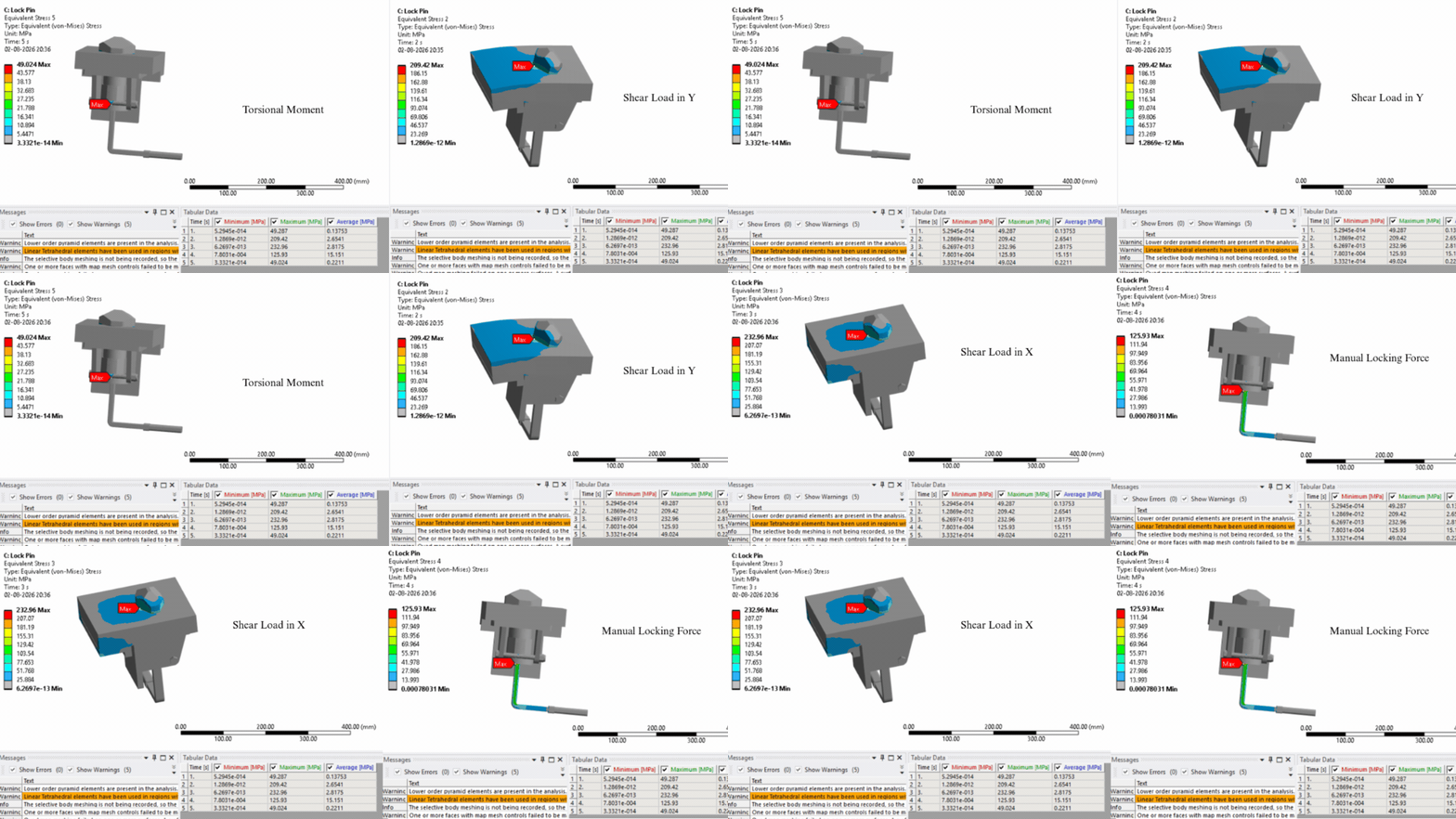
FEA Simulation — LS-3: Shear Load in X (Governing Case)
Material Properties & Load Steps
| Load Step | Applied Load | Max von Mises Stress (MPa) | Assessment |
|---|---|---|---|
| LS-1: Pin Preload | 2 kN bolt pretension | 49.287 | Below Yield |
| LS-2: Shear Load in Y | 86 kN, global Y-direction | 209.420 | Below Yield |
| LS-3: Shear Load in X | 86 kN, global X-direction | 232.960 | Below Yield |
| LS-4: Manual Locking Force | 250 N at handle | 125.930 | Below Yield |
| LS-5: Torsional Moment | 194 N·m about pin axis | 49.024 | Below Yield |
| Material | ASTM A572 Grade 50 Steel |
| Density | 7850 kg/m³ |
| Young's Modulus | 200 GPa |
| Poisson's Ratio | 0.30 |
| Yield Strength | 345 MPa |
| Ultimate Tensile Strength | 450–620 MPa |
| Friction Coefficient (Pin Interface) | 0.15 |
| Pin Radius | 15 mm |
Executive Summary
This case study presents a static structural Finite Element Analysis (FEA) of the lock pin assembly for a 35-ton tipper truck. The lock pin prevents the auxiliary frame from lifting away from the chassis while the tipper body is at its 30° tipping angle, resting on 8 lock pin assemblies.
A conservative design load of 86 kN was derived from the rated 35-ton payload (343,350 N), distributed over 8 pins (≈43 kN per pin) and factored by a dynamic factor of 2 for unloading operation. The assembly was evaluated across five load steps — pin preload, shear in Y, shear in X, manual locking force, and torsional moment — using ASTM A572 Grade 50 steel (yield strength 345 MPa). The analysis was carried out for Insight Design Consultant, with structural analysis performed by Santanu and Team and drawings prepared by Sumit Gorai.
Study Objectives
The FEA study was conducted with the following primary objectives:
FEA Simulation Observations
Pin Preload — LS-1
A 2 kN bolt pretension applied to simulate assembly preload and eliminate initial clearance produces a maximum von-Mises stress of only 49.287 MPa — well below the 345 MPa yield strength.
Shear Load in Y — LS-2
An 86 kN shear load applied in the global Y-direction produces a maximum von-Mises stress of 209.420 MPa, remaining comfortably below the material yield strength.
Shear Load in X — LS-3 (Governing Case)
An 86 kN shear load applied in the global X-direction produces the highest stress recorded across all load steps: 232.960 MPa. This remains below the 345 MPa yield limit but represents the governing (least-margin) load case for the assembly.
Manual Locking Force — LS-4
A 250 N force applied at the operating handle to simulate manual engagement produces a maximum von-Mises stress of 125.930 MPa, well within the elastic region.
Torsional Moment — LS-5
A 194 N·m torque applied about the lock pin axis, derived from the friction relation T = μFr at the 86 kN reaction force, produces a maximum von-Mises stress of 49.024 MPa, confirming adequate torsional capacity.
Load Case Stress Plots
LS-1: Pin Preload — 2 kN bolt pretension applied to simulate assembly preload.

LS-2: Shear Load in Y — 86 kN applied in global Y-direction.

LS-4: Manual Locking Force — 250 N applied at handle.

LS-5: Torsional Moment — 194 N·m applied about the lock pin axis.

Stress Profile by Load Step (vs. 345 MPa Yield)
Maximum equivalent (von-Mises) stress recorded for each load step, referenced against the ASTM A572 Grade 50 yield strength of 345 MPa.
Performance Evaluation Matrix
Design Load Basis & Derivation
The 86 kN design load applied to the lock pin assembly was derived through the following conservative design basis, rather than being applied as the full 35-ton payload directly on a single pin:
| Step | Basis | Result |
|---|---|---|
| Total Weight | 35,000 kg × 9.81 m/s² | 343,350 N |
| Load Distribution | Total load / 8 lock pins | ≈ 42,918 N (43 kN) per pin |
| Dynamic Factor | 43 kN × 2 (unloading dynamics) | ≈ 86 kN per pin |
| Selected Design Load | Conservative worst-case reaction | 86 kN (design assumption) |
| Friction Torque | T = μFr = 0.15 × 86,000 N × 0.015 m | 193.5 N·m ≈ 194 N·m |
Boundary Conditions
Engineering Recommendations
Maintain Separation of External Load and Torsional Load Cases
The 194 N·m torque is derived from the same 86 kN contact force through the friction relation (T = μFr). Applying both simultaneously in a single load case would effectively count the same loading effect twice.
- Use the 86 kN external load independently for standard structural strength assessment
- Reserve the 194 N·m torque for a separate analysis of the locking/unlocking mechanism under friction
Confirm Load Resolution When Applying Combined X-Y Loads
If 86 kN is applied simultaneously in both X and Y directions, the resultant load equals 121.6 kN. For an intended worst-case load of 86 kN total, resolve the load into its X and Y components rather than applying the full value in both directions.
Periodic Inspection at Governing Load Location
As LS-3 (86 kN shear in X) is the governing load case at 232.96 MPa, include this location in routine inspection schedules to monitor for wear, fatigue, or fastener loosening over the service life of the assembly.
Maintain 2 kN Preload During Assembly
Ensure the specified 2 kN bolt pretension is achieved and verified during assembly and periodic maintenance, as this preload eliminates initial clearance and contributes to the stable, low-stress response observed in LS-1.
Conclusion
The maximum equivalent stress obtained among all loading cases was 232.96 MPa under LS-3 (86 kN shear load in the X-direction). This value is lower than the material yield strength of ASTM A572 Grade 50 steel (345 MPa). Similarly, all other load cases — pin preload (49.287 MPa), shear in Y (209.420 MPa), manual locking force (125.930 MPa), and torsional moment (49.024 MPa) — produced stresses below the yield limit.
Therefore, under the applied loading assumptions, the lock pin assembly remains within the elastic region and is not expected to undergo yielding. The overall performance rating of 8.7 / 10 confirms that the selected lock pin assembly has adequate structural strength for the investigated loading conditions.